
iPhone Diagnostics and Troubleshooting Hub
Deep-Dive iPhone Tap to Pay and NFC Diagnostics Guide
In the real world of device repair, technicians frequently fall into the trap of replacing only the physical wireless NFC charging loop when Tap to Pay (Apple Pay) stops responding. However, Apple’s hardware ecosystem relies on a highly sensitive, intertwined chain of mechanical triggers, biometric authentication, and precise RF grounding pathways. If a single link in this loop is compromised during a repair, the entire Tap to Pay system goes down.
Use this comprehensive diagnostic matrix to quickly trace, test, and isolate hardware-based NFC failures directly from your repair bench.
🔍 Phase 1: Universal Diagnostic Triage (All Models)
Before cracking open a device, execute these baseline bench tests to isolate the root cause.
-
📲 Step 1: Check In-App vs. Physical Terminal Function
- Have the client attempt an in-app purchase (e.g., buying an app or adding funds in the App Store) using Apple Pay.
- ✅ Result A: If the transaction succeeds inside the app but fails at a brick-and-mortar checkout counter, the internal NFC chip, software loop, and Secure Enclave are perfectly fine. The issue is strictly an RF broadcast failure (a torn flex antenna, compromised frame ground, or bad contact points).
- ❌ Result B: If it fails both in-app and at a physical register, you are looking at a software loop, a logic board hardware fault (Secure Enclave IC), or a biometric loop failure.
-
🎧 Step 2: The "AirPod Range" Co-Symptom Test
- Connect a pair of Bluetooth headphones, slip the iPhone into a back pocket, and step 5 to 10 feet away.
- ❗ Result: If the audio cuts out, stutters, or drops completely, the upper chassis RF grounding path is broken. Because the Bluetooth and NFC antennas share adjacent grounding planes and frame loops, a weak Bluetooth signal is a dead giveaway. Do not waste time swapping the charging coil yet—focus on your upper motherboard grounding screws.
-
🔘 Step 3: Test Mechanical Initialization
- Lock the device and double-click the wake/power button (or Home button on Touch ID models).
- 🛑 Result: If the Wallet interface fails to launch from sleep mode, then the Side Button Flex is structurally torn or disconnected. The physical security gate cannot trigger the software, rendering Tap to Pay dead.
-
👤 Step 4: Verify Biometric Integrity
- Navigate to settings and ensure Face ID or Touch ID is fully operational without an "Issue Detected" pop-up.
- ❗ Result: If the front sensor array, Touch ID flex, or ambient light sensor is damaged, the Secure Enclave will actively refuse to supply power to the NFC controller chip as a hard security precaution.
⚙️ Phase 2: Model-Specific Architecture Layouts
Apple’s layout logic changes significantly across generations. Match the target phone to its architectural profile to pinpoint the exact failure points.
🧲 1. The Aluminum Unibody Era (iPhone 17 Series)
- The Layout: The NFC induction coil remains part of the center Wireless/Qi2 Charging Flex. However, because the phone features an aluminum unibody design with a prominent, raised aluminum "Camera Plateau", the top-edge RF loop bridges directly into the structural metal housing of the camera array itself.
- Primary Dependencies: Upper Display Sensor Flex, Side Button Flex, Camera Plateau RF ground clips.
- ❗ Real-World Nuance: Unlike the 16 Pro, the 17 series opens strictly from the front screen. Technicians no longer risk breaking NFC during back-glass removals on this model; instead, Tap to Pay failures are almost always caused by tearing the upper display-side sensor data lines or failing to properly seat the motherboard grounding screws when closing the screen.
🧲 2. The Glass MagSafe Era (iPhone 12 through iPhone 16 Pro Max)
- The Layout: The actual NFC induction loop is layered directly into the center Wireless Charging / MagSafe Flex. However, the critical broadcast hotspot is routed straight to the absolute top edge of the chassis right next to the rear camera housing.
- Primary Dependencies: Upper Wi-Fi/GPS Antenna Flex, Side Button Flex, TrueDepth Camera Array.
- Real-World Nuance: These modern, square-edged titanium and aluminum housings act as an extension of the NFC antenna. The entire loop relies on a delicate matrix of non-magnetic standoff screws on the upper camera shield cowling to bridge the circuit to the outer frame.
🔄 3. The Transition Era (iPhone 8 through iPhone 11 Pro Max)
- The Layout: These generations feature a distinct, standalone NFC/Bluetooth Flex Ribbon tucked into the top corner of the frame, entirely isolated from the main wireless charging pad.
- Primary Dependencies: Top-edge Antenna Flex, TrueDepth Flex, Power/Volume Button Ribbon.
- Real-World Nuance: The Bluetooth and NFC networks share a singular physical ribbon cable on these models. A careless slip of a spudger or a micro-scratch near the top-left motherboard standoffs will instantly kill both features at the same time.
🕰️ 4. The Classic Touch ID Era (iPhone 6 through iPhone 7 Plus, SE Series)
- The Layout: No MagSafe or center coils here. A dedicated NFC chip resides directly on the logic board, routing straight up to an Upper Left/Right Metal Antenna Bracket at the very top of the rear housing.
- Primary Dependencies: Home Button Flex, Charging Port Ribbon (for Touch ID data routing lines), Upper Metal Cowling Brackets.
- Real-World Nuance: The entire NFC signal strength relies on raw physical tension clips pressing firmly against the inside of the aluminum rear shell.
🔬 Phase 3: Step-by-Step Bench Inspection
When your preliminary triage points to a physical hardware failure, open the phone and follow this precise inspection checklist.
                  [ISOLATE TRAFFIC PATH]
                            │
            ┌───────────────┴───────────────┐
    [Check Bluetooth]               [Check Mechanics]
    Weak/Dropping Range?            Button Double-Click Fails?
            │                               │
    ┌───────┴───────┐               ┌───────┴───────┐
  [YES]            [NO]           [YES]            [NO]
    │               │               │               │
(Grounding      (Inspect NFC    (Replace Button (Check Biometrics/
 Screw/Shield    Coil/Ribbon     Flex Cable)     Secure Enclave)
 Failure)        Directly)
-
🔩 Step 1: Verify Shield Cowlings & Grounding Brackets
- Carefully inspect the upper metal shields covering the rear cameras and motherboard extensions. Check for missing grounding brackets—technicians doing fast housing swaps frequently leave these out, thinking they are purely cosmetic.
- Double-check every single screw. Never substitute a conductive, non-magnetic standoff screw with a standard logic board screw. Standard screws lack the specific alloy coating required to ground the NFC loop to the frame, causing the signal to drop to zero range.
-
🔌 Step 2: Inspect for Micro-Tears and Creases
- Examine the top-edge Wi-Fi/Bluetooth antenna ribbons under a microscope for hairline tears. Because NFC operates on a delicate 13.56 MHz frequency matching loop, even a microscopic edge nick will ruin the tuning circuit.
- On MagSafe models (iPhone 12–17 series), pay close attention to the fold where the wireless charging ribbon wraps over the edge of the logic board. Look for sharp, pinched creases caused by improper folding during a previous battery, screen, or internal component replacement.
-
⚡ Step 3: Check for Hidden Refurbishment Damages
- If the device is an iPhone 12 through 16 Pro and has undergone a heavy-handed back-glass repair using a laser machine, inspect the back of the wireless charging flex for hidden burn marks or melted copper tracks beneath the surface layer.
- If an aftermarket housing swap was performed (iPhone 6 through 16 Pro), check the inner screw holes. Low-quality aftermarket shells often feature heavy, insulating anodized layers or cheap alloy mixtures that isolate the grounding brackets, permanently blocking the Tap to Pay signal field.
- ❗ For iPhone 17 series: Laser damage and glass swaps do not apply due to the aluminum unibody design. Instead, inspect the outer frame corners for severe drop impacts or warps that might be physically separating the inner grounding clips from the structural aluminum Camera Plateau.
📊 Quick-Reference Component Matrix
| Symptom(s) | Probable Broken Component | Required Bench Action |
|---|---|---|
| ❌ Complete NFC dead zone + Wireless Charging is unresponsive | Wireless NFC Charging Flex Assembly | Replace the main center MagSafe/Wireless charging ribbon loop. |
| 📡 NFC reads only when smashed aggressively against a payment terminal | Upper Wi-Fi/Bluetooth Antenna OR Missing Grounding Screw | Check, clean, and reseat all upper camera shield grounding screws; inspect the top-edge antenna ribbon for micro-tears. |
| 🔘 Double-clicking the side button does absolutely nothing | Side Button / Power Button Flex Cable | Replace the mechanical side button click array ribbon assembly. |
| 🔄 Wallet UI launches but freezes infinitely on "Hold Near Reader" | TrueDepth Sensor Flex / Biometric Short Circuit | Disconnect the front proximity/ambient light sensor array to isolate the short circuit; replace if the data lines are looping the UI daemon. |
❗ Pro-Tip for the Bench: If a customer reports that Apple Pay works perfectly fine for online shopping or inside apps, but fails at physical store terminals, you can 100% rule out software bugs, Face ID errors, and the side button. The problem is an RF broadcast failure—look for a torn wireless charging/NFC flex, a severed top antenna, or a missing grounding screw!
📸 Visual Guide: Schematic Screw Type & Icon Key
When tracking down structural RF blockages under the microscope, cross-referencing your hardware layout with factory schematics is critical. Use the interactive placeholder below to map and display your visual layout references.
⚙️ Bench Map Placeholder: Swap the image 'src' attribute above with your target schematic file to embed it natively on your page.
- 🎯 Teal/Cyan Circle with Crosshair (+ with a solid center dot): Super Screws (Standoff Grounding Screws). These act as internal threaded anchors that ground the logic board and protective shield cowlings directly to the titanium or aluminum unibody frame. Missing or replacing these with generic steel screws completely cuts off the RF loop path required for terminal checkout tracking.
- ➕ Light Blue Circle with Plain Cross (+): Standard structural Phillips head screws. Used to maintain mechanical compression on shields and battery connectors.
- 📐 Dark Blue & Green Circles with Three-Lobe Propeller (Y): Tri-wing / Trilobe high-security internal screws.
- ⭐ Dark Blue Circle with 5-Point Star: External Pentalobe enclosure screws located alongside the charge port to anchor the display or structural unibody frame.
- ❗ Driver Ring Color Note: The outer ring colors on schematic maps indicate the precise color-coded factory torque driver required to safely secure the fastener without stripping threads or applying excessive torque to underlying logic board layers.
🔗 Master Screw Map Directory
To view the exact screw positions, structural configurations, and torque specifics for your repair, use the verified live document blueprints below (Choose Your Model → Repair Manuals → Screws inside each specific manual):
📚 All comprehensive hardware guides are indexed directly at the iPhone Manuals Hub (https://support.apple.com/en-us/docs/iphone) under Repair Manual then Screws.
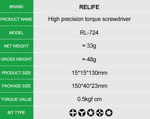
🪛 Required Drivers Reference Key
-

🟠 Orange Circle = Pentalobe (P2 / 0.8 mm)
Exterior Chassis Fasteners. Located on either side of the charging port.
-

🟢 Green Circle = Tri-wing / Y000 Security Screws
Motherboard Mounts (Strictly 0.2 mm), charging port shields, and delicate flex brackets.
-

⚫ Black Circle = Phillips #000
Heavier Components & Audio, including the speaker, Taptic Engine mounts, and bottom microphones.
-

🔵 Blue Circle = Grounding & Standoff Screws (Super Screws)
Layered Fasteners & Grounding Standoffs. These sit on top of one component to secure it while providing a threaded female top for a Tri-wing or Phillips screw to hold down an overlapping item.