
iPhone Diagnostics and Troubleshooting Hub
In the modern repair landscape, iPhones are incredibly integrated. A single torn sensor, a microscopic fracture in a flex cable, or a missing grounding shield screw can cause system-wide failures that mimic software glitches or entirely different hardware components. Understanding how these systems communicate is the key to executing clean, first-time-right repairs.
This master directory serves as a practical, hands-on bench resource. Below, you will find a breakdown of common on-screen warning icons and physical system alerts. Please note that these listings outline potential causes rather than absolute, definitive diagnoses. This is intended as a helpful guide to steer your troubleshooting in the right direction. Browse the expandable categories below to get started on your bench diagnostics.
Common Faults and Decoding On-Screen Diagnostics / Warning Icons
When an iPhone encounters a hardware bottleneck, iOS triggers specific visual indicators or failure loops. While these signs are not definitive proof of a single component failure, recognizing them helps identify potential trouble spots and guides your multimeter or hardware isolation testing toward the correct subsystem. Below is the Franchitti's Fix guide to decoding common physical component faults and iOS hardware panic signals:
Physical Component Failures (Visual Diagnostics)
Ink-like black bleeds, dead touch zones, or bright vertical lines (commonly green or pink on OLEDs) indicate a physically fractured inner display panel or a damaged flex cable neck. This requires a complete screen assembly replacement, even if the outer front glass remains perfectly intact.
If your screen is visibly pushing out of the frame or the device no longer sits flat on a table, the lithium-ion battery cells are producing gas and swelling. This is a severe fire hazard. Do not press the screen back down; immediately replace the battery to prevent permanent damage to the display panel.
A compromised back panel is not just a cosmetic issue. Deep structural cracks break the device's original IP-rated perimeter seal, directly exposing the delicate wireless charging coil, rear camera modules, and logic board to immediate moisture and particulate damage.
A bent frame, dented corners, or broken structural joints will prevent replacement screens and back glass from sitting flush. Ignoring chassis warping during a repair guarantees the new glass will sit under constant tension, leading to immediate stress fractures upon minor impact.
iPhones utilize multiple microphones. If callers cannot hear you on a standard phone call, suspect the primary mic on the lower Charging Port Flex. If audio is distorted during speakerphone calls or rear camera video recordings, the fault lies with the rear mic (often located on the power button flex or rear camera bracket).
If you see permanent dark spots or faint grey circles in your photos (especially visible against a solid white background), the internal image sensor is contaminated with microscopic dust or debris. Because these camera modules are factory-sealed, the entire rear camera assembly must be replaced.
If the rear camera continuously pulses or fails to focus on Pro/Pro Max models, the LiDAR (radar) depth sensor is likely impaired. A damaged sensor is common after drops, but if the back glass was recently replaced with a cheap aftermarket panel lacking the proper IR-transparent filter, the laser will bounce back, effectively blinding the sensor.
The device powers on to the Apple logo, goes black, and repeats indefinitely without triggering a panic log. Often caused by a liquid-damaged earpiece sensor flex shorting the internal data bus, or a severely degraded battery failing to deliver the peak amp draw required to boot. On newer iPhone models, a damaged or liquid-corroded barometric sensor can also stall the boot sequence.
iOS System Alerts & Panic Logs
Often mistaken for a pure software crash. On Face ID devices, liquid damage to the flood illuminator on the Earpiece Sensor Flex will force the device into recovery mode. If hardware isolation fails, suspect a corrupted firmware partition or failing logic board NAND IC.
Triggered when thermistors detect extreme heat or simply lose connection. If the phone is physically cold but showing this error, check for a severed gas gauge line on the Battery Connector or a corroded thermistor on the Charging Port Flex.
Usually caused by liquid ingress shorting the earpiece speaker array, or physical tearing of the fragile front sensor flex during a screen repair. The dot projector and infrared camera must maintain perfect alignment and electrical continuity.
A watchdog timeout on the I2C bus. If the logic board pings a sensor (like the lower microphone on the charging port, or the power button thermal sensor) and gets no reply, it kernel panics and reboots exactly every 3 minutes to protect the system.
Occurs when serialized components are replaced without transferring the original IC chips or using Apple's System Configuration tool. The device functions normally, but features like True Tone or Battery Health percentage will be disabled in Settings.
The system detects an abnormal impedance bridge across the CC or data pins inside the charging port. Caused by moisture, lint accumulation, or permanent pin corrosion. Often requires a full Charging Port Flex Replacement if cleaning fails.
Results in a permanent "No Service" or "Searching..." status. Almost exclusively a board-level issue. Often caused by drop impact fracturing the solder joints between the sandwiched motherboard layers, severing the Baseband Power Management IC.
A buzzing/rattling feeling usually means loose Taptic Engine mounting screws. A completely dead engine indicates a failed actuator coil, or a torn Charging Port Flex Cable, which provides the physical contact pads for the Taptic Engine.
If the speakerphone icon is unclickable during calls, the system cannot detect audio hardware. On older models (iPhone 7/8), this is classic "Loop Disease" (Audio Codec IC failure). On newer models, suspect a torn lower Charging Port Dock Flex.
Because the rear camera module and the flash LED often share a common power delivery rail, a hardware short circuit in the flash flex will frequently disable the camera entirely to protect the circuit. Depending on the iPhone model, the flash may be on its own dedicated flex, integrated into the power button ribbon, or attached to the camera bracket.
The Ambient Light Sensor (ALS) is damaged or obscured. This is typically caused by a torn earpiece flex or missing EEPROM serialization data. Additionally, installing a budget aftermarket LCD onto a natively OLED device will block the sensor; LCDs require a solid backlight layer and cannot replicate the transparent sensor window found on OLED panels.
Diagnostic Tip: Always perform "Hardware Isolation." Before attempting logic board micro-soldering, temporarily plug in a verified working peripheral (like a new charging port flex or screen) without fully installing it into the chassis. If the error clears, you have isolated the faulty component.
🪛 Required Drivers Reference Key
-

🟠 Orange Circle = Pentalobe (P2 / 0.8 mm)
Exterior Chassis Fasteners. Located on either side of the charging port.
-

🟢 Green Circle = Tri-wing / Y000 Security Screws
Motherboard Mounts (Strictly 0.2 mm), charging port shields, and delicate flex brackets.
-

⚫ Black Circle = Phillips #000
Heavier Components & Audio, including the speaker, Taptic Engine mounts, and bottom microphones.
-

🔵 Blue Circle = Grounding & Standoff Screws (Super Screws)
Layered Fasteners & Grounding Standoffs. These sit on top of one component to secure it while providing a threaded female top for a Tri-wing or Phillips screw to hold down an overlapping item.


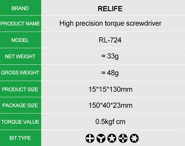
ReLife
ReLife RL-724 High Precision Torque Screwdriver
Share


🔩 Universal iPhone Screw Guide
iPhone screws aren't just holding the phone together—they are active parts of the device's electrical and wireless circuitry. Mixing them up is the number one cause of permanent motherboard damage (known as "long-screw damage") and broken features.
This universal guide breaks down the color coding used on our interactive repair maps.
(Note: Exact screw counts and structural locations vary by model. For precise blueprints, check our model-specific diagnostic pages!)
📱 iPhone Anatomy: What to Expect
🧲 Magnetic Property Note
Unlike the specialized non-magnetic standoffs found in the upper chassis (used to protect the camera's OIS and compass), the 🔵 Cross Torque / Standoffs in the lower chassis are typically magnetic. While this makes them easier to extract with a magnetized driver, you must still map them meticulously to avoid swapping them with standard ⚫ Phillips screws.
🔼 Upper Chassis: The Sensor & Camera Suite (Top Half)
⚠️ CRITICAL MOTHERBOARD WARNING
The top of the phone is the most sensor-heavy area in the entire device. The motherboard screw mounts in this zone ONLY accept 0.2 mm Tri-wing (🟢) screws. Inserting any other size, length, or thread type will drill directly into the logic board layers beneath it, permanently destroying the device.
It is incredibly easy to accidentally run a long screw into a logic board trace or a delicate flex cable here, which can permanently disable core iOS features. Always use a segmented magnetic organizer mat to track your hardware.
The Sensors in this Zone
- TrueDepth Camera Array: On iPhone 12 and newer models, the front-facing FaceTime camera, infrared camera, flood illuminator, and dot projector are structurally consolidated into a single unified physical module. (On iPhone 11 and older models, the FaceTime camera and TrueDepth Face ID components remain physically separate modules connected to the board via distinct ribbon cables.)
⚠️ Damage Warning: Never touch the exposed lenses of the dot projector or infrared camera. Tearing this flex cable during bracket removal will permanently disable Face ID because this module is cryptographically paired with the logic board. - Ambient Light Sensor (ALS) & Proximity Sensor: Measure light levels to control auto-brightness and detect when the phone is held to your ear to turn off the screen during a call.Design Evolution: Older screen designs (iPhone 11 and prior) utilized 🟢 Tri-wing screws extensively along the screen frames. Newer screens removed most of these; iPhone 12 through 16 models secure the ALS module using 1-3 ⚫ Phillips screws, while iPhone 17 and later models have reverted to 1-2 🟢 Tri-wing screws.
⚠️ Damage Warning: Even with screws removed, these sensors are lightly adhered to the display bezel. Aggressive prying can easily rip the micro-soldered traces, permanently breaking auto-brightness and True Tone. - Front-Facing FaceTime Camera: Captured alongside the sensor array.
⚠️ Damage Warning: Highly susceptible to airborne dust and fingerprint oils. Avoid wiping the lens with dry microfiber or harsh solvents, as they can scratch or strip the anti-reflective coating. - Rear Camera Array: Non-Pro models feature a dual-lens (Wide and Ultra-Wide) setup. In contrast, Pro models feature a triple-lens array equipped with delicate, magnet-stabilized Optical Image Stabilization (OIS) coils.
⚠️ Damage Warning: The internal OIS magnets are incredibly fragile. Bringing highly magnetized heavy tools too close or dropping the module can shatter the mechanical stabilizers—leaving the camera permanently blurry or vibrating. Ensure you secure these brackets with the correct designated hardware (⚫ Phillips for standard brackets, 🟢 Tri-wing for Pro shields). - The LiDAR Scanner: Exclusive to Pro models (12 Pro through 17 Pro), this sensor emits invisible laser pulses to map 3D depth. It assists with instant AR measuring and speeds up low-light camera autofocus by 6x for Night Mode portraits.
⚠️ Damage Warning: The optical emitter grid is highly sensitive to misalignment. Avoid applying direct downward pressure to the scanner module when reseating the rear camera bracket. - Upper Microphone: Used for video recording, noise cancellation, and speakerphone calls.
⚠️ Damage Warning: Poking sharp tweezers or metal spudgers too deeply into the upper housing alignment slots can instantly puncture the delicate acoustic microphone membrane. - Wi-Fi, Bluetooth & GPS Antennas: Highly delicate flex cables running along the top and upper-left edge of the frame.
🧲 Non-Magnetic Requirement: These antennas require strictly non-magnetic screws in the correct positions to function properly. Introducing magnetic hardware here causes electromagnetic interference that will severely degrade your Wi-Fi, Bluetooth, and GPS signals.
⚠️ Damage Warning: These ribbon cables are folded tightly against the chassis and are usually secured with non-magnetic 🟢 Tri-wing screws. A single slip of a tool can slice clean through them, permanently crippling wireless signal strength.
⚠️ The Screw Hazard
Many of the screws securing the upper camera and sensor connector brackets look identical to the naked eye but have microscopic length differences. Putting a screw that is even 0.2 mm too long into a 🔵 Standoff hole can drill straight through the logic board layers beneath it, permanently severing vital trace lines and instantly killing the phone. Never rush the reassembly of this zone.
- TrueDepth Camera Array: On iPhone 12 and newer models, the front-facing FaceTime camera, infrared camera, flood illuminator, and dot projector are structurally consolidated into a single unified physical module. (On iPhone 11 and older models, the FaceTime camera and TrueDepth Face ID components remain physically separate modules connected to the board via distinct ribbon cables.)
🔋 The Center Core: Power & Wireless Fields (Middle)
The middle section of the iPhone is engineered to manage the flow of physical and wireless energy.
The Components in this Zone
- The Logic Board & Ultra-Wideband (UWB) Chip: The brain of the phone. Most modern iPhones use a dual-layer "sandwich" board design. Built directly onto this board is the UWB Chip, which acts as a precision radar for inches-accurate tracking. Secured by strictly 0.2 mm 🟢 Tri-wing screws at the mounts and various 🔵 Standoffs.
⚠️ Damage Warning: Flexing the dual-layer board during removal will snap internal micro-solder joints, causing boot-looping or dead touch. As with the top half, driving a screw longer than 0.2 mm into a 🟢 Tri-wing mount will instantly kill the board. - The Battery: A heavy lithium-ion cell secured with stretch-release adhesive pull tabs. Its connector shield is typically secured by 🟢 Tri-wing or ⚫ Phillips screws.
⚠️ Damage Warning: Slipping with a tool near the battery can puncture the lithium-ion cell, leading to dangerous thermal runaway and fire. Never use sharp metal pry tools along the edges of the battery. - Wireless Charging & NFC Antenna Loop: Located directly behind (underneath) the battery, adhered to the back glass. The outer ring transfers wireless power, while the small embedded NFC loop broadcasts the 13.56 MHz frequency.
⚠️ Damage Warning: Tearing the delicate flex cable connecting this loop to the motherboard will permanently disable Apple Pay, Tap to Pay, and wireless charging. - Physical SIM Tray vs. eSIM: Located on the side of the chassis. International models feature a physical SIM reader and tray, whose shield is usually secured by 🟢 Tri-wing screws.
⚠️ Damage Warning: If you mix up the screws securing the shield over the SIM reader, you will crush the motherboard traces beneath them, resulting in a permanent "No SIM" error. - 5G mmWave Antenna Window (US Models Only): High-frequency 5G mmWave signals cannot pass through metal. On US models, a small, oval-shaped plastic window is carved into the metal frame, housing a dedicated antenna flex secured by 🟢 Tri-wing screws.
🧲 Non-Magnetic Requirement: The screws securing this antenna bracket are strictly non-magnetic. Introducing magnetic hardware here will cause radio frequency interference, severely degrading 5G speeds.
⚠️ Damage Warning: Slicing the flex cable behind this window with a pry tool will permanently disable high-speed mmWave connectivity. - Action Button (iPhone 15 Pro, 16 & 17 series): Located on the upper-left rail, this programmable solid-state button replaced the old mechanical toggle switch. Secured by ⚫ Phillips or 🟢 Tri-wing screws depending on the model year.
⚠️ Damage Warning: The micro-switch and its attached flex cable are incredibly fragile. Prying carelessly during frame swaps will tear the ribbon and break the button's functionality.
- The Logic Board & Ultra-Wideband (UWB) Chip: The brain of the phone. Most modern iPhones use a dual-layer "sandwich" board design. Built directly onto this board is the UWB Chip, which acts as a precision radar for inches-accurate tracking. Secured by strictly 0.2 mm 🟢 Tri-wing screws at the mounts and various 🔵 Standoffs.
🔽 Lower Chassis: Power, Audio & Haptics (Bottom Half)
The bottom of the phone is a high-vibration area that handles physical user feedback, sound output, and physical plug-in power.
The Components in this Zone
- Exterior Pentalobe Fasteners: The two anchor screws at the very bottom of the frame. Historically used exclusively to secure the screen assembly. Model Note: On the iPhone 14, 14 Plus, 15 series, 16 series, and 17 series, these screws are dual-purpose and are also routed to hold the removable rear glass panel.
📏 Length & Compatibility Warning: While the left and right screws on a single phone are the same length, Pentalobe lengths and thread pitches vary across different iPhone models. Never mix Pentalobe screws from a parts bin; forcing an incorrect screw will strip the internal frame threads.
⚠️ Damage Warning: Failing to use a dedicated, high-quality 🟠 Pentalobe driver will strip the delicate, shallow star-shaped heads. Stripped bottom screws are nearly impossible to extract and usually require precision drilling, which poses a massive risk of shattering the screen or back glass or scratch the metal finish. - Taptic Engine & Solid-State Home Buttons: The high-speed linear actuator motor that generates haptic vibrations. The motor itself typically mounts to the frame using exactly three screw points, secured by a combination of ⚫ Phillips screws and 🔵 Cross Torque / Standoffs (which then provide a threaded top for a secondary screw to hold down an overlapping bracket).Model Note: On the iPhone 7, 8, and SE (2nd & 3rd Gen), the Home Button does not actually click physically. It is a solid piece of glass; when pressed, the Taptic Engine fires instantly to fake a mechanical "click" sensation.
⚠️ Damage Warning: Failing to properly torque these three screws will cause the engine to rattle violently against the frame, eventually destroying the motor. - Camera Control Button (iPhone 16 & 17 series): Embedded on the lower-right rail, this is a flush sapphire-glass button. It combines a mechanical click switch, a force sensor for light presses, and a capacitive swipe sensor to let you slide your finger to zoom or change camera lenses.
⚠️ Damage Warning: The capacitive and force sensor flex is extremely delicate. Using excessive force or heat near this rail during battery removal can melt or sever the flex. - Main Loudspeaker Chamber & Bottom Microphones: The acoustic box providing audio output, alongside high-sensitivity mics used for voice calls. Usually secured by ⚫ Phillips screws.
⚠️ Damage Warning: Inserting tools too deeply into the bottom speaker or microphone grilles from the outside of the phone will permanently puncture the waterproof acoustic mesh and destroy the microphone membrane. - Charging Port Assembly: The physical USB-C (iPhone 15 and later) or Lightning (iPhone 14 and earlier) dock connector flex cable. Often secured by a mix of 🟢 Tri-wing and ⚫ Phillips screws.
⚠️ Damage Warning: Ripping this massive flex cable during removal will kill charging, bottom microphones, and loudspeaker functionality all at once.
- Exterior Pentalobe Fasteners: The two anchor screws at the very bottom of the frame. Historically used exclusively to secure the screen assembly. Model Note: On the iPhone 14, 14 Plus, 15 series, 16 series, and 17 series, these screws are dual-purpose and are also routed to hold the removable rear glass panel.